How Do You Choose Fittings for custom hydraulic hoses?
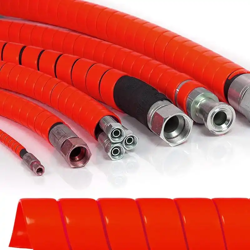
Choose fittings for a custom hydraulic hose by matching six items: hose series, working pressure, end connection, sealing method, material, and installation geometry. ISO 18752:2025 covers hydraulic hose classes from 3.5 to 56 MPa and states that an assembly is limited by its lowest-rated component. A fitting that threads into a port can still be wrong if its seat, pitch, or seal differs. JIC uses a 37° flare, ORFS uses an O-ring face, while NPTF relies on tapered threads. Confirm the hose-and-fitting combination against the manufacturer’s crimp specification before assembly, especially above 3,000 psi.
Start with the hose rather than the fitting catalog. A custom hydraulic hose may use textile reinforcement, one or two wire braids, or multiple spiral-wire layers, and fittings designed for one construction cannot automatically be transferred to another. The stem diameter, ferrule profile, insertion depth, and final crimp diameter are developed around a particular hose construction.
Pressure provides the first practical filter. ISO 18752:2025 defines 10 pressure classes, from 3.5 MPa to 56 MPa, or roughly 508 to 8,122 psi, and covers nominal hose sizes from 5 mm through 102 mm. The standard also states that the maximum working pressure of an assembly is governed by the component with the lowest permitted pressure.
That rule prevents a common purchasing error: choosing a 5,000 psi hose and assuming every attached fitting creates a 5,000 psi assembly. SAE J517 applies the same principle to hose assemblies using fittings covered by standards such as SAE J516, J518, and J1453; the lower applicable pressure rating governs the assembly.
Pressure rating alone does not describe fatigue performance, so pressure cycling comes next. ISO 18752 classifies hoses by impulse resistance; published performance categories include 200,000, 500,000, and 1,000,000 minimum impulse cycles, with testing commonly conducted at 120% or 133% of maximum working pressure depending on class and grade.
A hose used at 3,000 psi on equipment that cycles hundreds of times per hour has a different service profile from a 3,000 psi line that remains pressurized with limited movement. Fitting retention, hose construction, routing, temperature, and impulse qualification should therefore be considered together.
Once pressure requirements are known, identify both ends independently. Hose size does not automatically equal port size: a -8 hose normally represents a nominal 1/2-inch ID, yet the assembly may use a -8 fitting at one end and a different connection size at the other.
| Connection | Typical sealing surface | Thread behavior | Identification point |
|---|---|---|---|
| JIC | 37° metal flare | Straight | Check flare angle and thread |
| ORFS | Flat face with O-ring | Straight | Check face seal and O-ring groove |
| SAE ORB | O-ring at port | Straight | Check thread and O-ring position |
| NPTF | Thread interference | Tapered | Check TPI and taper |
| BSPP | Cone, washer, or bonded seal | Parallel | Check 55° thread form and seal |
| BSPT | Thread interference | Tapered | Do not identify as NPT by diameter alone |
| Metric DIN | Often 24° cone | Metric | Measure diameter and pitch |
The thread form matters because visually similar connectors may use different geometry. Parker technical data identifies NPTF with a 60° thread angle and BSPT with a 55° thread angle; a 1/2-inch NPTF connection, for example, uses 14 threads per inch. A caliper alone cannot reliably distinguish every connection.
Use three measurements when an existing fitting is unknown: thread diameter, pitch, and sealing surface. A 3/4-16 thread found on a common 1/2-inch JIC connection does not describe the hose ID by itself, and the 37° flare must still match the mating connection. Parker’s assembly examples pair a -8, 1/2-inch hose with a 1/2-inch female JIC connection using a 3/4-16 thread.
Sealing location should then decide how the connection is assembled. JIC fittings seal at the 37° metal surfaces; ORFS seals at the compressed O-ring on the fitting face; ORB uses an O-ring against a machined port; tapered pipe connections form their seal differently. Thread engagement is therefore not proof that two ends belong together.
Do not add thread sealant to a fitting simply because a connection leaks. A damaged JIC seat or ORFS O-ring will not be repaired by coating the threads, because those threads are not the intended sealing surface. Inspect the actual seat, O-ring, groove, and mating face before replacing parts.
Temperature narrows the selection further. ISO 18752:2025 lists oil-based hydraulic-fluid ranges of -40°C to +100°C for AS, AC, BS, and BC types, while CS, CC, and DC types extend to +120°C; listed water-based fluids are generally covered from -40°C to +70°C.
Temperature limits need to include both fluid and surroundings. A hose carrying oil at 80°C can still sit near an engine or exhaust surface that raises external exposure considerably, while equipment starting outdoors below 0°C places different demands on the tube, cover, and seals. Gates therefore treats fluid temperature and ambient temperature as separate selection inputs.
Material follows the environment. Zinc-plated carbon steel is common on mobile and industrial hydraulic equipment because of its strength and cost, while 316 stainless steel is available for assemblies exposed to salt, frequent washdown, or corrosive process environments. Parker, for example, identifies steel, brass, and 316 stainless steel as fitting-material options in its hose assembly ordering system.
Seal material needs the same attention as the fitting body. Mineral oil, water-glycol fluid, phosphate-ester fluid, biodegradable hydraulic fluid, and water do not place identical requirements on elastomers. ISO 18752:2025 specifically separates temperature ranges for oil-based fluids, water-based fluids, and water, and places fluid compatibility responsibility on the user in consultation with the hose manufacturer.
After material selection, look at routing. Straight fittings work when the hose can leave the port without an immediate sharp bend; 45° and 90° elbows can reduce unnecessary curvature where space is restricted. Gates installation guidance specifically recommends angled fittings or adapters where routing would otherwise force the hose below its required minimum bend radius.
A tighter hose is not a better installation. Hydraulic hose changes slightly in length under pressure and needs enough free length to flex without pulling against the fitting. The same guidance warns against excessive hose length, bending below minimum radius, twisting hoses through two planes, and clamping high- and low-pressure lines together.
Two elbow fittings add another measurement: angular orientation. Parker specifies displacement angle when two elbows are installed on one assembly and gives a 270° orientation as an example in its ordering system. Without a recorded angle, a correctly sized 2026 replacement hose may reach both ports but place one elbow in the wrong direction.
Crimp compatibility should be checked before any hose is cut. The correct fitting series must match the specific hose series, and the workshop should use the prescribed die set, insertion depth, machine setting, and finished crimp diameter. A ferrule that appears tight provides no numerical confirmation that reinforcement has been compressed within the approved range.
The completed crimp should therefore be measured rather than judged visually. Manufacturer crimp tables normally identify a target diameter or acceptable range for each hose-and-coupling combination; changing hose series while retaining the previous machine setting can change compression even when both products carry the same -6, -8, or -12 nominal size.
Treat the hose, coupling, ferrule, and crimp specification as one tested assembly. ISO 18752:2025 covers 10 pressure classes and multiple performance grades, while SAE J517 separately defines requirements for common SAE hydraulic hoses; neither supports selecting components only because they physically fit together.
Length should be recorded after the fitting style is chosen. Parker measures overall hose-assembly length to defined fitting reference points and notes that elbow assemblies are measured to the fitting centerline in relevant configurations. Replacing a 36-inch assembly by cutting exactly 36 inches of bare hose will therefore produce the wrong finished length.
For a repeatable order, record hose ID, hose series, working pressure, maximum fluid temperature, fluid type, overall assembly length, end-A connection, end-B connection, fitting angles, and elbow orientation. Add abrasion sleeve, fire sleeve, spring guard, or other protection only where the routing and environment call for it.
A workshop receiving an unknown assembly should also inspect thread damage, sealing faces, corrosion, ferrules, and hose cover condition before copying it. An old fitting may have been replaced incorrectly years earlier, so duplication should not override dimensional identification or the current manufacturer specification.
For equipment operating around 4,000 psi, a useful selection sequence is pressure and impulse requirement first, hose construction second, connection identification third, fluid and temperature compatibility fourth, and routing geometry fifth. Crimp data and finished dimensions follow only after those inputs agree, reducing the chance that a visually compatible fitting becomes the limiting component in service.